Some remarks in English, so that Ludvik, Radim, Mirek etc. could read them easily... and I could write more quickly.
One of the possible uses of the system is replacing the cold water in the oil-heated boiler (supplying the manufacture with hot water and vapour) with the hot water from the large solar tank, to spare heating it up by oil at the beginning of the work in the juice plant. It would be easy when the whole system would contain the same softened (or inherently soft, from rain) water. That's just some 1.5 cubic metre and would be useful twenty times a year perhaps. Full range of the buffer temperatures would be used after each one-week pause of the juice plant.
More heat could be employed by preheating the water going to the boiler from the pasteur. It's temperature is 70 degrees, the boiler supplies 105 degrees, so more than half of the heat could be solar-supplied when having 90 degrees at the upper part of the main buffer.
The total heat flux to the pasteur is up to some 80 kW, as up to 1000 l/h of the juice can be pasteurized by heating the juice from say 10 to 80 degrees. A typical flux, when not tanks but just bottles are filled with juice, is perhaps 50 kW. The possible solar coverage is therefore from 25 to 40 kW. Assuming 5 cubic metres of juice being pasteurized in one day, the buffer could really supply half of the heat when over 90 degrees down to the bottom. Full sunshine could almost prevent the buffer from cooling, when just the bottles are filled by juice.
The water returning to the buffer could flow to the appropriate height perhaps just through a bored polypropylene pipe.
Such a direct connection of the buffer with the boiler raises some problem of keeping the boiler temperature. Namely, the constant pressure at the top of the boiler would be some 0.4 bar due to the height of the buffer, whereas the switch-off pressure corresponds to just 0.5 bar. It should be however easy to make the switch-on pressure to be over 0.4 bar (it's perhaps 0.3 bar now).
There is an easy possibility to be a supplier instead of a consumer of heat when the heating plant is working and there are solar surpluses at the site.
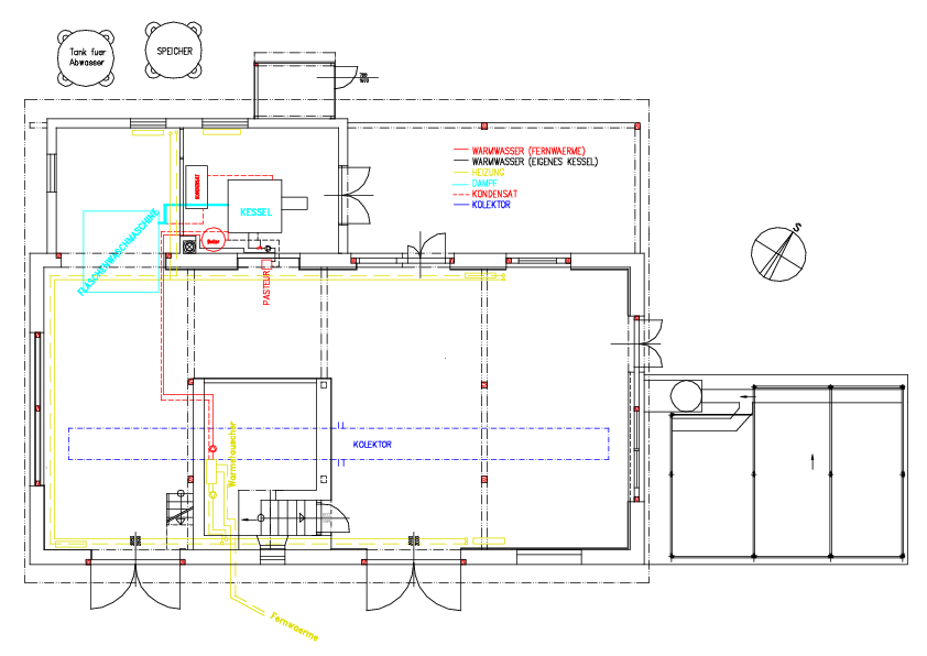
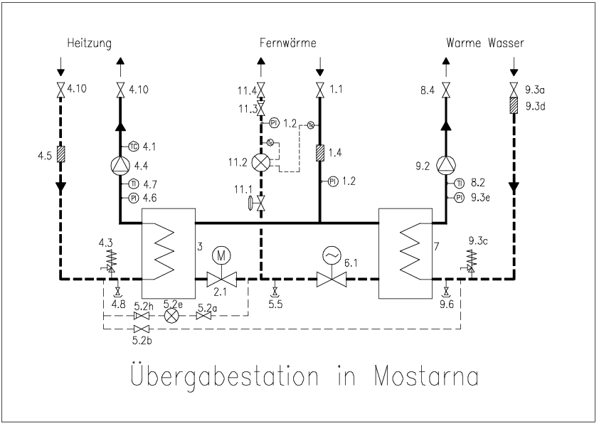
The existing warm-water-heating pipes in the building should do perhaps, they have just to be prolonged till the buffer. (Both building plan - pipes.pdf or pipes.png - and conveyor station plan - conv_sta.pdf or conv_sta.png - show them as going from the right side of the conveyor station, however the photos1show they are connected to its left part in fact.) And of course they have to be connected to the main plate heat conveyor for supplying the net with a sufficient heat flux of at least 30 kW.
The pump to be added should overcome up to 1.5 bar of static pressure difference, a bit more to overcome the dynamic pressure loss in the thin 15mm network connection, say 2 bar together. The village network hot pipe is at almost 80 degrees currently, it could be at 70 or even 65 degrees outside freezing periods in future, to make the losses lower and the solar support more efficient. (The network guaranty demands just the maximum being not over 80, no limits regarding any temperature changes.)
For the summer period, when the whole network is not running, there appeared an easy possibility to supply heat to a short branch which goes just up from the central square (down right, i.e. SE, I call it south later in the text, at the last photo of photos, the juice plant is at top left corner of the scheme), just a bit westwards from the branch going to to the juice plant. There are five family houses to use the heat on that branch, not all are equipped with a water-heated tank at the moment - but they will buy it of course, as the district heat is cheaper than electricity (the tinox-supplied heat in summer could be still twice cheaper perhaps). A larger pipe proceeds to the west and south again, but as it goes sufficiently down the slope behind the municipal hall, no convection losses can happen in this direction.
There is one another customer (Janota) branched some metres eastward along the main pipe, it is not yet sure if his connection goes from the top or the side of the main pipe - if from the top, it would become an important consumer with three boilers currently (two flats and the shop). This main pipe goes almost horizontally here, so the losses to distant parts of it should remain low.
Even another consumers could be tried, but they are rather far and on sloped parts of the main pipe (to the east, toward the heating plant). To the western side (behind the branch to the south) the main pipe dives below the stream, leaving not much chance to get the warm water through, but forming a perfect syphon to prevent convection losses in this direction.
I believe the losses in the network should remain below the usefully supplied heat. Even for the future, when the network should run once a day or two in summer, using (say, a rapeseed-oil) co-generation engine at the end of the net, the losses will be not much less, as the amount of water in the network is some 100 l per house, comparable with the size of the boilers in the houses themselves.
will be a considerable one, in the future, when the Centre will be erected and used. Before that, we should improvise some spas in the garden for the volunteers working in Hostetin. Even the only shower inside the building could be used by lots of people in fact.
It seems to me that it is possible to use the large buffer as an expansion tank as well - either simply by letting some 1 cubic metre empty at the top at the beginning, or by filling it with nitrogen afterwards, to avoid oxygen. Still, over 9 cubic metres would remain for the water. Of course, the water would dissolve some gas, but as the top would be the hottest part, no gas would be released elsewhere in the piping. The only place where the gas would be released is the heat conveyor from the solar circuit, it should be done in such a way that the released air would travel back to the top of the buffer.
I don't know if an expansion cavity is done this way sometimes, and if a check of the amount of the gas remaining there would suffice once a year, I think it should (having two pipes, one going from beneath the desired water surface and one from above it).
Three stratifying pipes are needed probably: one for the existing Juice plant collector, the other for the future Facade collector on the Centre, and the third one the water returning from the pasteur (or from the village heat supply, when the whole net works). From the heating system inside the plant or from the warm water system there, the returning water would be so cold, that it perhaps could return simply to the bottom of the buffer.
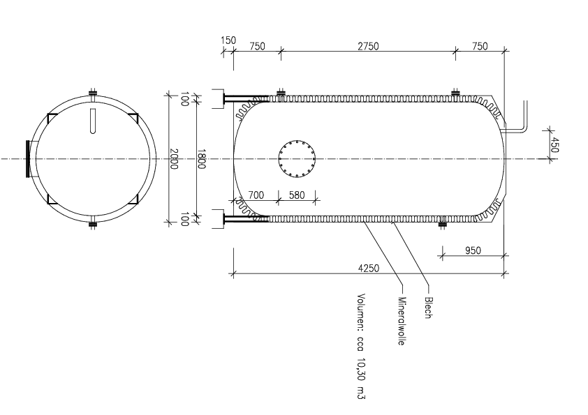
The image of the tank, tank_ori.pdf or tank_ori.png, shows the original thin mineral wool insulation, there is none any more now. We plan to insulate the tank with at least 50 cm straw (up to 80 cm, depending on the size of the bales). An ideal strawbale installation, as it will be dried all the time. Dry straw is lambda 0.04 definitely, if the heat flows perpendicularly to the straws.
Before the insulation, any ev. pipes should be welded to the sides. But, do we need any such pipes? At the top, there is I think one outlet, it should do perhaps. Or, should we make another one as well?
As for the temperature sensors, I suppose we can install them even afterwards, using a thin metal pipe as a long hollow needle.
On the walls, there should be perhaps four or five rings welded around the circumference of the tank, at each metre of the tank's height. Or what exactly should be welded there? As it can be easily welded by an electrode to the thick wall, it can be made even inside the insulated tank.
From the bottom, perhaps seven pipes should go, three of them thick, for the stratifying (bored) pipes. What size? I suppose that all the vertical pipes inside the tank could be PP ones, just firmly attached to the short steel pipes going through the bottom of the tank. We could weld there even later, when the walls will be insulated already.
I hope we would build the strawbale cylinder around the tank mid-July already, with a tile roof and a wooden or even just clay-plastered surface.
Jenik, June 19